

Cabling and Connectivity for Power-over-Ethernet
Power over Ethernet (PoE) has made great strides in recent years. Driven by the demand for ease of installation and boosted by new standards that expand support to more devices, PoE is expected to see explosive growth rates that match the period shortly after the technology was initially introduced in 2003.
There are some appealing reasons for adopting PoE. Foremost, by running power and data transmission over the same cable, PoE eliminates the need for additional wiring installations, saving on money and redundant cabling. This consolidation also allows for faster deployment at the endpoint, especially to devices at far off building locations such as warehouse transactions work areas, security cameras, sales kiosks, etc. And remote power feeding allows power to be consolidated into one central location.
Standards Overview
While earlier standards limited the types of devices that could be supported by PoE, recent standards have allowed for higher power transmission, expanding the range of devices supported in the enterprise and in turn further driving adoption rates. However, higher current PoE brings important cabling and connectivity considerations when ensuring utmost performance in the network.
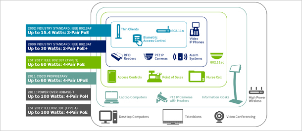
- In 2002, IEEE published the 802.3af standard, which outlined Power over Ethernet at up to 15.4 W of DC power, while supporting 10BASE-T and 100BASE-T. Power was delivered over two of the four twisted pairs of Cat 3 cable or higher.
- In 2009, IEEE introduced 802.3at, also known as the "PoE+" standard. This update allows delivery of up to 30 W, and supports 1000BASE-T over CAT 5 or 6. It also limited power transmission to two of the four cabling pairs. While PoE+ switches support devices that require higher power, they can also detect devices requiring 15 Watts or less and deliver the appropriate level required.
- In 2011, Cisco created a non-standard PoE implementation called Universal Power over Ethernet (UPOE). UPOE can use all four cabling pairs and supply up to 60 W, further expanding the types of devices that can be supported.
- In April 2013, IEEE announced the study group for creating 802.3bt, which will define PoE over four pairs and support 10GBASE-T. The new standard will define two tiers of PoE: Type 3 will support up to 60 watts, and Type 4 up to 100 watts, for devices requiring higher power, such as laptops and TVs. The publication date for 802.3bt is expected in early 2017.
- Power over HDBASET (PoH). HDBASET delivers video, audio, 100Mbit/s Ethernet, and power. The POH standard is based on the 802.3at standard, modified to enable delivery of up to 100 W over 4-pair Cat 5e or 6.
- TIA and ISO are also currently updating standards that address cabling to support 4-pair PoE in accordance with 802.3bt. TIA TSB-184 Guidelines for Supporting Power Delivery Over Balanced Twisted-Pair Cabling and ISO/IEC 11801-6 Distributed Building Services working draft are raising requirements to Category 6A cabling to better support IEEE 802.3bt four-pair PoE, as well as other applications.
Equipment for Delivering PoE
A PoE system has two primary components: Power Sourcing Equipment (PSE) and a Powered Device (PD). The PD receives its power from the PSE using standard Ethernet cabling. The PSE can be divided into two types: endspans and midspans. Endspans are essentially Ethernet switches with PoE circuits added, while midspans are positioned between the switch and the powered device.
Midspans, also known as PoE injectors, are typically used when PoE is the only upgrade being made to the network, such as when adding IP phones or wireless apps to an existing non-PoE network. This avoids replacing switches that do not offer PoE but are still within their productive life cycles. Midspans may be located anywhere, as long as they are installed in a standard compliant facility, such as a telecommunication room or enclosure, and are not installed as a part of a permanent link.
Cabling for PoE
One of the biggest issues that can affect performance is heat generation in cable bundles. When power is added to balanced twisted-pair cabling, the copper conductors generate heat and temperatures rise. The heat dissipates into the surrounding area until a stable temperature is reached, with the cable bundle at a higher temperature than the surrounding ambient temperature. High temperatures can lead to higher insertion loss and in turn shorter permissible cable lengths, as well as higher power costs due to more power dissipated in the cabling. As recent PoE standards allow for higher power transmissions, temperature concerns will likely become even more prevalent.
Cable temperatures should not exceed the temperature rating for the cable, and cables for commercial typically have a maximum temperature rating of 60 degrees Celsius. The Telecommunications Industry Association (TIA) recommends 15 degrees as the maximum allowed temperature rise above ambient as a result of power over the cabling.
The TIA suggests a number of ways to help lower cabling temperature:
1. Reduce the number of cables per bundle
Separating large cable bundles into smaller bundles or avoiding tight bundles will minimize higher temperatures. For example TIA tested the temperature of a bundle of 91 cables, and then separated that bundle in to three bundles of 37. The temperature in the center of a 91 cable bundle was higher than the worst case temperature in centerpoint of three bundles. Physically separating the three bundles from each other further reduced the maximum temperature.
2. Use Higher Category Cabling
Higher category-rated cable typically means larger gauge sizes, and as power currents increase, these larger conductors will perform better than smaller cable. Figure 1 shows TIA testing that compares temperature rise to increasing cable bundle size for different category ratings and their wire gauges. All cables were tested using a current of 1000 mA per pair. The test shows that higher category-rated cable allowed for larger bundle sizes under the maximum 15-degree temperature increase. The allowable bundle size was 52 cables for Cat 5e, 64 for Cat 6, 74 for Cat 6A, and a similar increase for Cat 8.
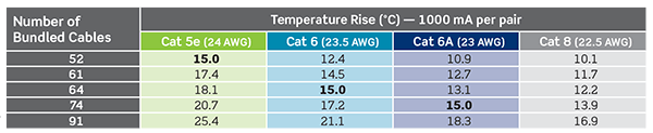
Figure 2 compares the temperature rise in 100 cable bundles of Category 5e, 6, and 6A, as the current per pair increases (over all four pairs). Again, the higher-category cabling is able to support more current capacity at the maximum allowable 15 degrees, as the Category 6A bundle supported 865 mA per pair. It becomes clear that higher category cabling will be necessary to minimize temperature increases while supporting PDs that require more power. For this reason Leviton recommends using Category 6A for new 4-pair PoE applications.

3. Install Shielded Cabling
Leviton engineers recently tested how heat affected performance in Leviton Category 6A cabling. They compared three cable types: Unshielded Twisted Pair (UTP), Foiled Unshielded Twisted Pair (F/UTP), and cable using Leviton patented Noise Canceling Helix Technology (NCHT). NCHT cable includes a metallic "isolation wrap" that surrounds the 4-pair core, and features separations in the wrap to prevent a current from flowing along the length of the cable. This isolation wrap provides additional alien crosstalk suppression, but eliminates the need for grounding and bonding typically required with shielded cabling.
The samples of cable were tested carrying a PoE+ current of 600 mA per pair over all 4 pairs at an ambient temperature of 60 degrees Celsius. Each cable type was coiled into a separate 90 meters length and terminated with jacks at both ends. They then applied the current while monitoring the temperature rise of the bundle.
If the test result passed insertion loss requirements from TIA-568-C.2 and ISO/IEC 11801 Class EA, they would end the test for that cable type. If the result failed, they removed 1 meter of cable from the coil, re-terminated, and re-applied the current, then took another measurement. They continued this process until obtaining a passing result.
The insertion loss length de-rating varied considerably between the cables tested, as listed in Figure 3. The UTP cable exhibited the worst performance, as it required more than 9 meters of length to be removed before it returned a passing insertion loss result. The F/UTP and NCHT cables performed significantly better, with the NCHT cables requiring only 1 meter of length removed, and the F/UTP cable still passing at 90 meters.
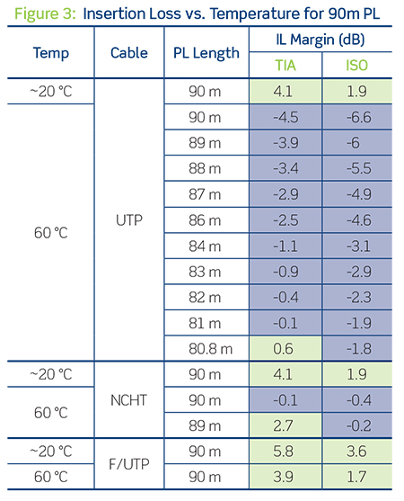
The large difference in performance between UTP and the other cables at elevated temperatures is likely because UTP cable has no shield or isolation wrap barrier between the insulated conductors and the outer cable jacket material. In turn, there may be an interaction that changes the dielectric constant around the conductor and contributes to greater attenuation at higher temperature.
It is important to note that while insertion loss varied between F/UTP and NCHT cable types, there are pros and cons for every cable type. While F/UTP fared the best, NCHT offers the benefit of no grounding or bonding, and it is easier to terminate. These considerations should be made based on your specific network application.
Connection Reliability
Another consideration with higher current PoE is the potential for damage over time to RJ-45 connectors in the network. Specifically, when a patch cord is unplugged while the connection is charged, an electrical arc will occur between the connector and the plug. While there is no immediate damage (and the arc is not dangerous to users), the integrity of the connection can become weakened over numerous disconnections.
To add extra protection and longevity to the life of the connection, Leviton recommends using connectors with 50 μm gold-plated tines (as specified by TIA standards), as well as designs that distance the connection point between the connector tines and plug from the arcing damage. They should also meet contact resistance requirements found in the IEC 60512-99-001 standard covering connectors for electronic equipment.
Leviton tested the placement and severity of pitting on the Leviton connector tine set resulting from electrical arcing across the contacts when plug and connector are disconnected in an energized PoE+ application. The test found that pitting developed on both the connector tines and the plug contacts after 25 insertion cycles, with increased damage after an additional 25 cycles with reversed current flow.

However, the location of the pitting in Leviton connectors is sufficiently far from the point of contact between the tines and plug contact when the connectors are mated, as shown in Figure 4. This means that the pitting does not affect the electrical performance of the connectors within a channel, providing additional longevity.
About Leviton Copper Cabling Systems
High-quality connectivity is essential for attaining the performance, reliability, and flexibility needed in today's network operations. Leviton is dedicated to delivering the highest performing cabling systems to support infrastructure in mission-critical networks, small-to-large business enterprises, and residential units.
Leviton copper system connectors, patch cords, and patch panels are component rated, and third-party tested and verified to exceed industry standard performance. And qualifying system installations are backed by a limited-lifetime warranty. You can always expect to receive maximum return on infrastructure investment (ROii™) when you choose Leviton connectivity.
Learn more at Leviton.com/copper
Recent Posts
Tags
Home (89)
Electrical (80)
Safety (59)
Networking (46)
Home Improvement (38)
Residential (34)
Data Center (31)
lighting (28)
Home Automation (28)
Energy Savings (24)
Fiber (24)
Dimmers (24)
Leviton (24)
GFCI (21)
receptacles (21)